How to interface adc0808 with 8051 microcontroller
The following circuit diagram shows the required 8051 microcontroller circuit.
ADC0808 has 8 input channels so at a time 8 sensors can be connected. You can use any channel for ADC purposes in the code. A potentiometer (i-e variable 10k resistor) is connected on IN1 of ADC0808 just to demonstrate how to use this code. Input voltage at IN1 is read in the code and displayed on the LCD. ADC0808 gives an output of 8bit value, so a voltage value of 0v at IN1 will mean ADC value of 0 and a voltage of 5v at IN1 pin means ADC value of 255. In the above figure, it is clear that a voltage of 2.5v is applied on IN1 pin and ADC value of 127 (i-e half of 255) is displayed on the LCD correctly.
A crystal of 12MHz value is used in this circuit, which makes this 8051 (i-e AT89C51) run at a speed of 1MIPS .
In the while(1) loop, ADC_Value = ReadADC(AN1); statement reads value from IN1 pin of ADC0808 and assigns this value to ADC_Value variable. Next 3 statements are converting ADC_Value in to digits, which will be displayed on the LCD screen. After that, LCD screen is cleared and ADC value is displayed on the LCD.
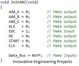
InitADC() function is shown below.
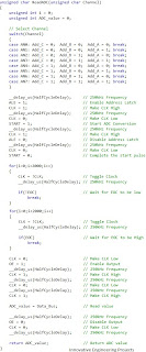
ReadADC() function code is shown below.
The following circuit diagram shows the required 8051 microcontroller circuit.
In this circuit, 8 bit data bus of ADC0808 is attached with 8051 on Port 0. control signals of ADC0808 are connected on Port 2 of 8051 micro controller. LCD is connected on Port 1, LCD is used to show the output of ADC.
ADC0808 has 8 input channels so at a time 8 sensors can be connected. You can use any channel for ADC purposes in the code. A potentiometer (i-e variable 10k resistor) is connected on IN1 of ADC0808 just to demonstrate how to use this code. Input voltage at IN1 is read in the code and displayed on the LCD. ADC0808 gives an output of 8bit value, so a voltage value of 0v at IN1 will mean ADC value of 0 and a voltage of 5v at IN1 pin means ADC value of 255. In the above figure, it is clear that a voltage of 2.5v is applied on IN1 pin and ADC value of 127 (i-e half of 255) is displayed on the LCD correctly.
A crystal of 12MHz value is used in this circuit, which makes this 8051 (i-e AT89C51) run at a speed of 1MIPS .
Code
The code is shown below.
In the main function, firstly pins attached with ADC0808 are initialized using InitADC(); statement, then LCD is initialized using InitLCD() function. Then "Starting..." is displayed on the LCD for one second. After that LCD screen is cleared.
In the while(1) loop, ADC_Value = ReadADC(AN1); statement reads value from IN1 pin of ADC0808 and assigns this value to ADC_Value variable. Next 3 statements are converting ADC_Value in to digits, which will be displayed on the LCD screen. After that, LCD screen is cleared and ADC value is displayed on the LCD.
InitADC() function is shown below.
In the InitADC() function shown above, pins attached to ADC0808 are initialized properly. Also, data bus attached with Port 0 is initialized as well.
ReadADC() function code is shown below.
ReadADC() function (shown above) returns 8 bit ADC value. This value is read from a channel, which is the input argument to ReadADC() function. Channel can have a value of AN0 for IN0 pin of ADC0808 or AN1 for IN1 pin etc. For example, to read voltage value at IN7 pin of ADC0808, you can use the statement ReadADC(AN7);.
This is all about 8051 with adc0808


No comments:
Post a Comment